DCC++
Round about 2013 Gregg E Berman developed a DCC control system based on an Arduino Uno microcontroller board. I required additional motor control board and a couple of jumper wires to complete the device. Although it worked well it needed a computer (desktop or laptop) to run the system.
DCC-EX 
 In 2020 a team of enthusiasts got together and decided to completely rewrite the DCC++ software to run on the more powerful Arduino Mega controller board. This enabled them to provide many ports to receive signals from sensors and issue commands to external devices such as signals and turnouts. This new development was originally called DCC++EX but is now known as DCC-EX.
All the software is open source and free as was the original DCC++ system.
This resource aims to explain how to source and build your own DCC-EX system.
For full information about the DCC-EX system please go to the DCC-EX web site.
Build Your Own
Parts List
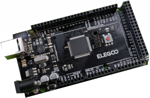
- Arduino Mega R3 – eBay £15 – AliExpress £11
- DeekRobot Motor Driver Shield – eBay £15 – AliExpress £4.80
- EX-WiFiShield 8266 – Chesterfield Models & Miniature Electronics £17
- 9V 1A Power Supply – eBay £6
- 15V 4A Power Supply – eBay £14 – MERG £14 (members only)
N.B. Prices as at February 2026
You will also need to have access to a computer for setup, a smartphone (Android or Apple iPhone) for day-to-day running, and appropriate leads and wires for connecting things up.
Putting it Together
These instructions are for building a 1.5A output EX-CommandStation. This will be OK for running a few OO locomotives. If you need a higher output you will need to use a different motor driver board. See below for details.
Modify the Motor Driver Board
 Before you start you need make a simple modification to the motor driver board. The board is designed to power the Arduino Mega as well as the motors etc.. Although the motors will work normally with 15V or so the Arduino Mega is only designed to take a maximum of 12V on the DC input plug.
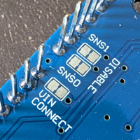
Underneath the motor board are several metal pads. Locate the pair labeled VIN CONNECT. Cut and scrape away the small metal trace that joins the two pads. You can check your work using a multi-meter set to resistance mode. You should find an open circuit . If not scrape a bit more away.
Plug the Motor Driver Board into the Arduino Mega
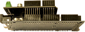 There are two rows on pins on the motor driver board that match up with the sockets on the Arduino Mega. You will notice that there is a slight gap in the rows of pins and sockets. This helps you to be sure that you have the boards the right way round. Take great care to get the two boards aligned correctly and take especial care that the pins slide into the sockets and do not bend and slip down the side.
Check your work!
Plug the WiFi Board on Top
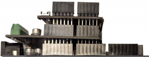 In the same way as with the motor driver board it is now time to plug the WiFi board on top. As before, take care to align the pins correctly.
Connect the WiFi board to the Arduino Mega
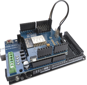
The Arduino Mega needs to be able to communicate with the WiFi board. This is done using the short two wire male/female jumper normally supplied with the WiFi board.
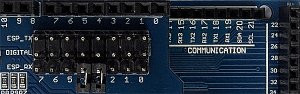 The Arduino Mega needs to be able to communicate with the WiFi board. First remove any small pin jumpers on the three rows of pins on the WiFi board. Now connect the pin in ESP_TX row, column 0 to socket RX 19 on the Arduino Mega and the pin in ESP_RX row, column 0 to socket TX 18 on the Arduino Mega.
The physical construction of the DCC-EX Command Station is now complete.
Installing the Software
The easiest way to install the software is to use the EX-Installer. You can download the EX-Installer from the DCC-EX web site. You will find full instructions there. They will not be duplicated here as they may change or be updated from time to time.
Alternative Motor Driver Boards
If you need higher current output that the basic motor driver board provides then you will need to fit an alternative one. The fitting broadly follows the instructions above but with minor alterations. For full information see the DCC-EX web site.